In a previous post I described the mechanical construction of a new gate for Chitterne. In this post I will provide an introduction to its control electronics.
Let me start by saying that I fully accept that the gate control mechanism described below is ludicrously over complicated. My only defence is that it does at least work and that once I came up with the idea it became a challenge to prove to myself that it was possible.
Issues with previous solution
The original gate mechanism used a simple 9g servo and a control board from Dingo; I observed two problems:
- The motion of the gate was not smooth but instead it kept stopping and then jerking forward.
- The gate often failed to complete a full 90° of motion leaving it either not fully closed or – worse – not fully open and liable to snag on passing traffic.
I resolved to design a control system which would address both of these issues.
Servo speed control
I discovered that there is a fundamental problem with driving small servos at slow speeds. In summary, the motor is driven so slowly that it frequently stalls. Eventually the control system kicks it into action again and this causes the unsteady motion.
The solution was to replace the internal servo controller with my own electronics. Since I was going to measure the gate position directly (see later) I removed everything from the servo except the motor and gearbox. I then constructed my own motor drive circuit using “Back EMF” to regulate the motor speed.
The Pi Pico microcontroller produces a pulsed voltage to drive the motor. During the “off” periods of this waveform it measures the back EMF voltage from the motor which is proportional to the motor speed. It then adjusts the driving pulses to compensate for any unwanted speed variation.
The motor drive is measured and updated 200 times per second so as soon as the motor starts to stall it is immediately kicked back into motion before the effect is visible. By using this controller I was able to drive the servo smoothly at speeds of less than one revolution per minute.
My foolish idea
To achieving an accurate 90° of motion, it occurred to me that what really matters is the position of the gate, not the angle of the servo. Furthermore, the gate has to stop when it reaches the post at each end of its travel; ideally, it would slow down as it approaches. So, the thing I need to determine is “How far is the gate from the post?” It was my resolve to measure this parameter directly which lead to this foolishly complex solution.
A simpler solution would be an electrical contact between gate and the post, but this would require an unpainted section. It also wouldn’t give me any way of measuring the gate position to allow the gate to slow down before contact.
I considered various mechanisms including optical and magnetic sensors, but in the end capacitance seemed the way to go. Since the gate was already metal, if I made two metal gate posts then I could measure the capacitance between the gate and the posts. As the gate approaches a post this value will increase and give me a way of measuring the “gap”.
Fiddling with femtofarads
I did some rough calculations and concluded that the capacitance would be very small even when the gate was practically touching the post. Also, measuring a very small capacitance would require a sensitive circuit which would be susceptible to interference from mains hum, track voltages, light fittings, mobile phones and a host of other sources.
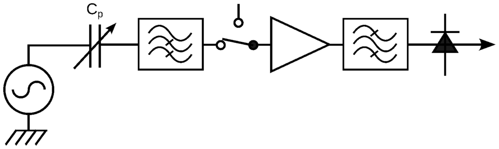
There are several different ways to measure capacitance. The one I chose tries to pass a signal through the capacitor. As the capacitance increases, the effective impedance of the capacitor goes down and more signal will get through. For very small capacitors like this you have to use a high frequency signal to get any through at all and I settled on 10.7 MHz. This is a standard frequency used in radio receivers so suitable components are readily and cheaply available – particularly so in my garage!
The diagram below shows the basic concept. A 10.7 MHz oscillator (left) is connected via the gate to post capacitance, Cp, which varies as the gate moves. The signal then passes through a high pass filter to remove the biggest interference such as mains hum and track voltage before meeting a switch which selects between the two posts. It is then amplified, passed through a bandpass filter to remove any other interference and converted to DC with a detector circuit. The resulting output voltage is related to gate position and is measured by an ADC in the microcontroller.
Implementation
The entire system is controlled from a Pi Pico microcontroller. This might not be the ideal controller, but it has the required functionality, is very cheap, easy to programme and I already had one to hand.
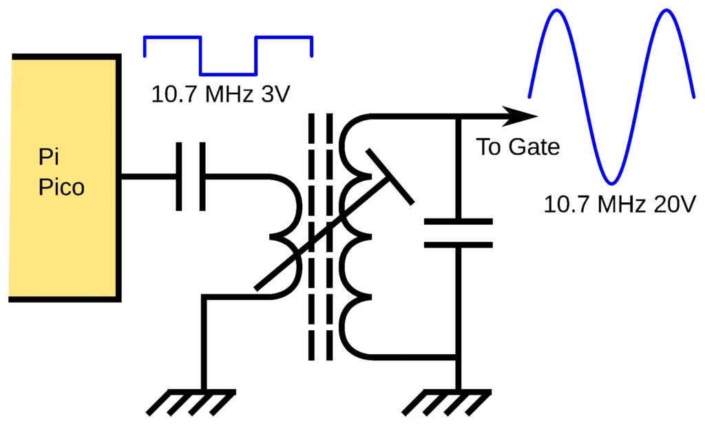
I programmed the Pi Pico to generate a 10.7 MHz signal at 3 V and used a tuned transformer to increase this to about 20 V.
The diagram below is a simplified version of the receive circuit. The initial capacitor and resistor form the high pass filter. The switch and amplifier are combined into a single IC sold as a video multiplexer. Final filtering uses a 10.7 MHz ceramic filter with about 100 kHz bandwidth. A conventional envelope detector circuit produces the DC output voltage.

Prototype and production
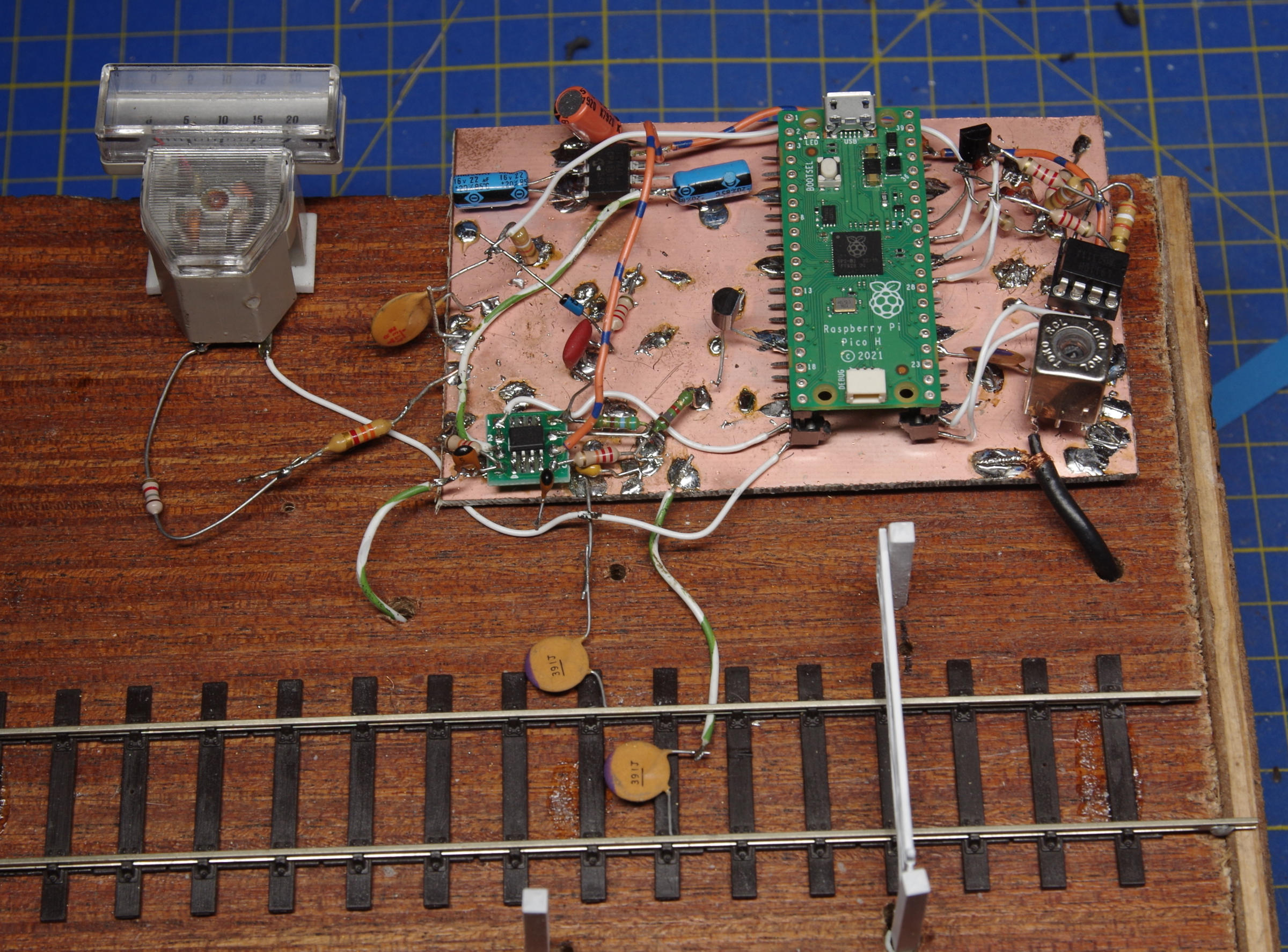
I computer simulated some parts of the circuit using SPICE and then set about constructing a prototype. I used my favourite technique of 3D construction over a ground-plane. This is less flexible than using a conventional breadboard, but works better for circuits with high frequencies and small signals. I combined this with the gate and a small section of EM gauge track on a simple wooden frame as shown in the photo below. The small meter indicates received signal strength for testing and demonstration purposes and isn’t included in the final design.
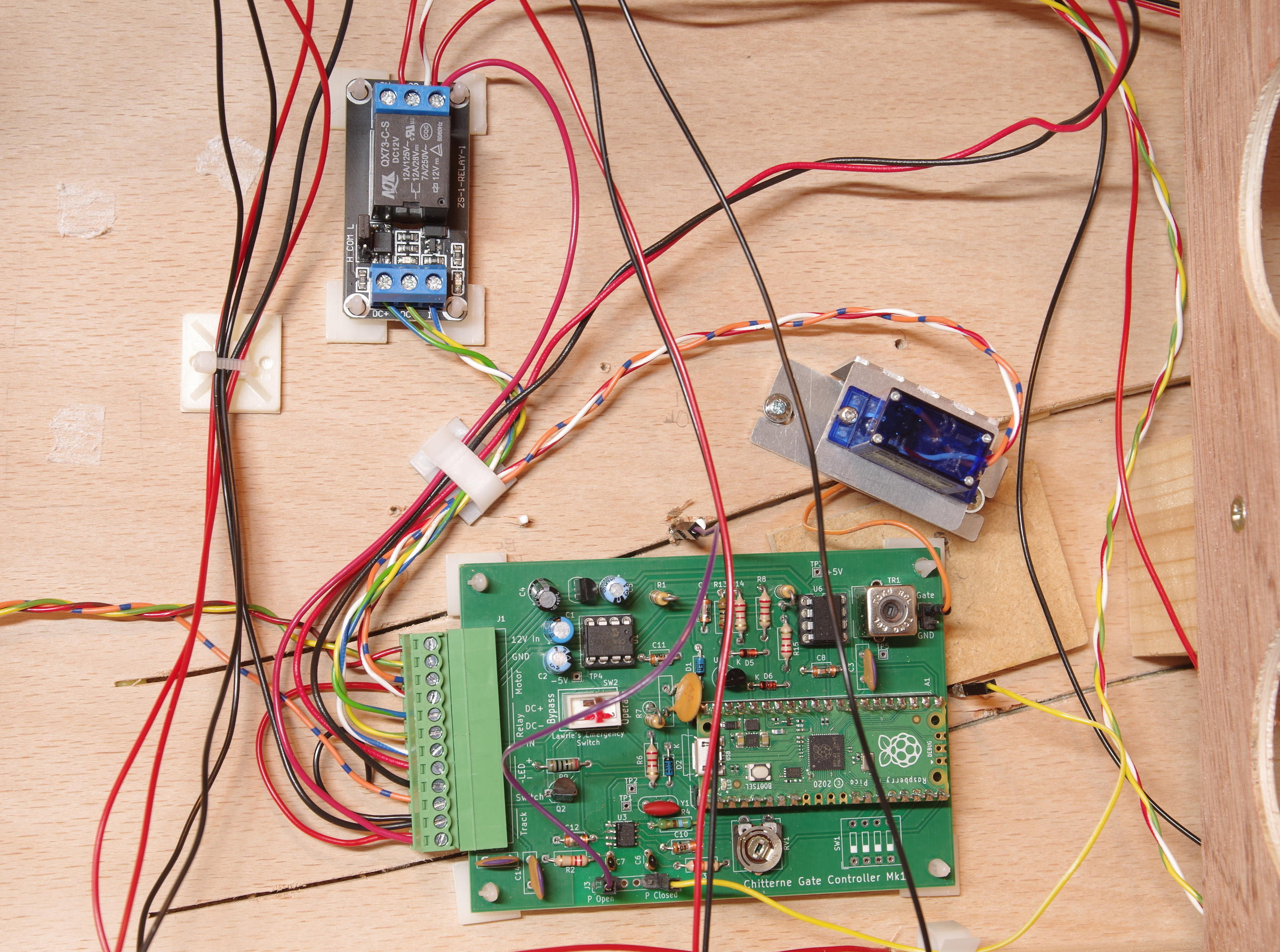
With the circuit finalised, I moved onto designing the production version using my KiCAD EDA software. I didn’t include the track voltage relay as I already had several small relay PCBs which I purchased for almost nothing from a strange charity shop in Andover which sells brand new industrial components. I also included an external LED for diagnostics.
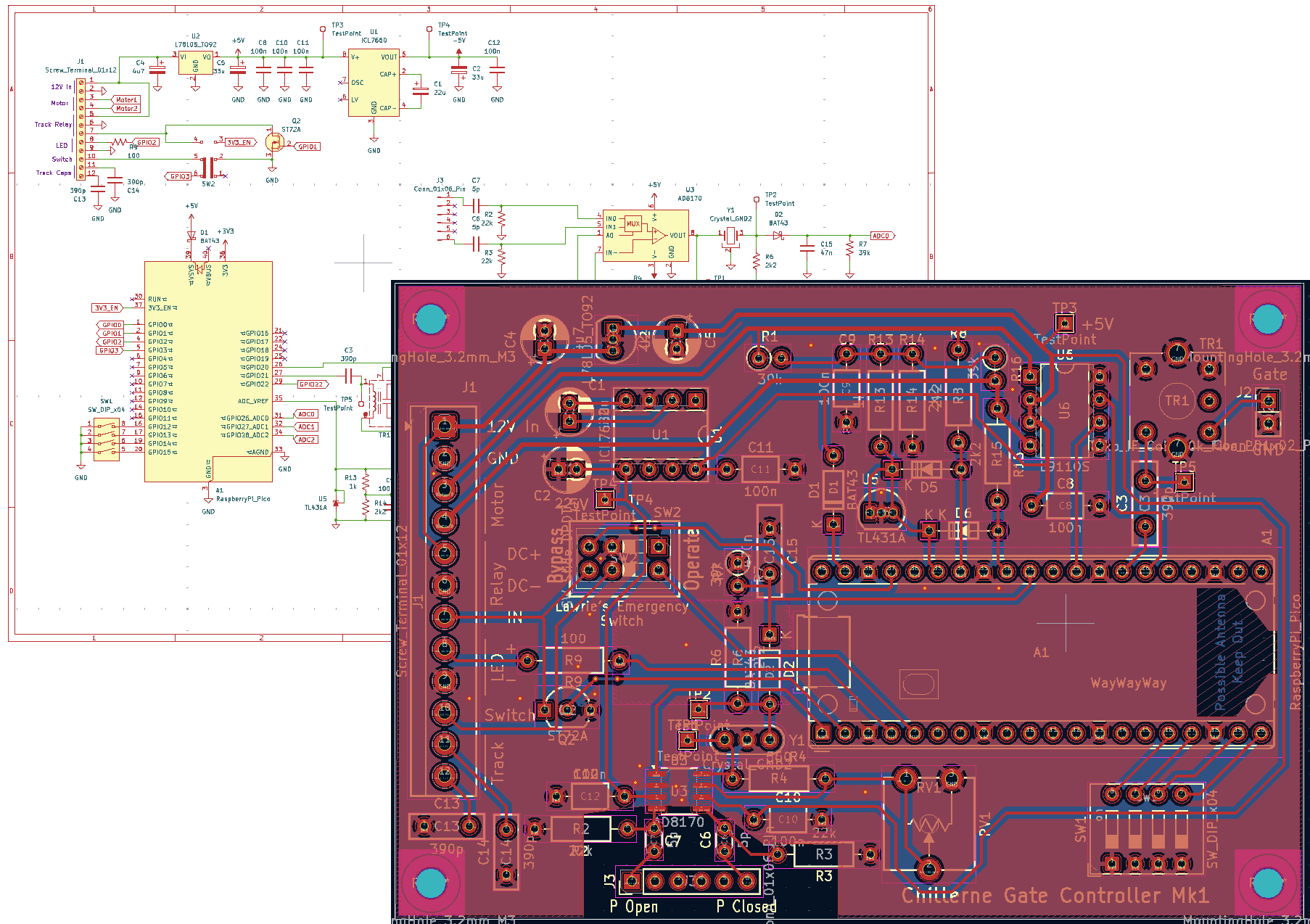
I ordered the PCB from PCBWay with whom I was most impressed. With their special offer for small simple PCBs and a $5 new customer discount, the total cost for five PCBs (minimum order quantity) was £3.70 including postage from China which took only six days! After assembling the PCB, I was astonished to discover that it worked first time!
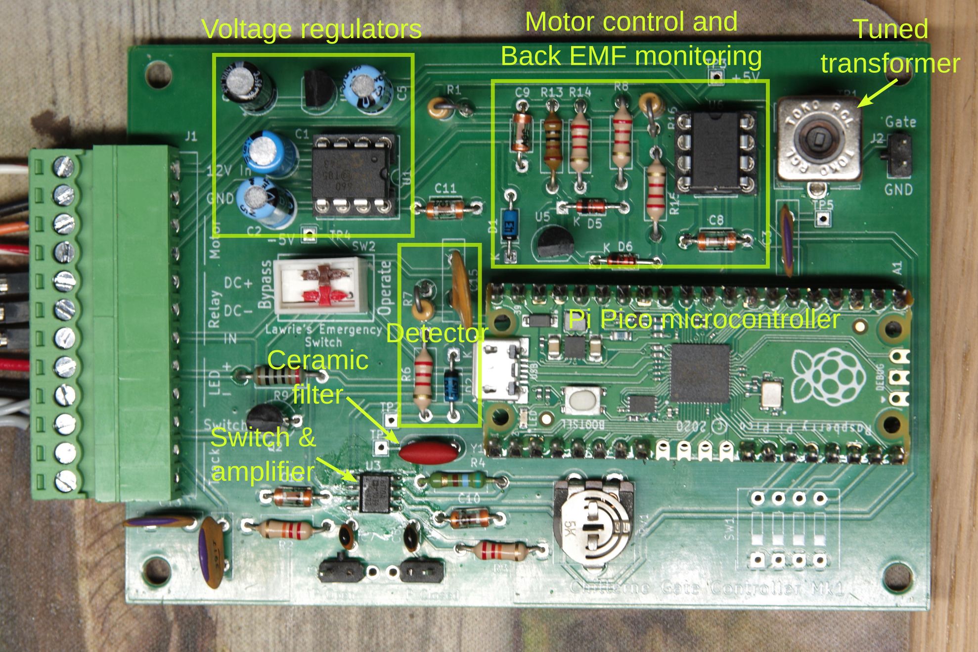
The white block just below the voltage regulators is a bypass switch to disable the control system in case of problems during a show. There are actually two switches; one disables the Pi Pico to prevent any motor movement and the other connects the control panel switch to the track relay so that it directly controls track power. Since Lawrie was particularly insistent that I include such a feature, I named it after him!
Software
The Pi Pico can be programmed using either MicroPython or C++ and I settled on the former as it is quicker to write and adequate for a task of this complexity.
The control program contains two main loops. The first monitors the back EMF and controls the motor voltage to maintain a commanded speed. This uses a classic PID control algorithm provided by a library I downloaded.
The second loop measures the gate position and sets the demanded motor speed. The current version sets the speed based on the received signal from the gate post with a stronger signal producing a slower speed with a maximum limit. The net effect is that as the gate starts to move away from the post the signal falls and the speed increases to the maximum. This continues until the gate approaches the next post where the signal increases again causing the speed to reduce until the gate reaches the post.
The software has a “Motion too long” fault detection algorithm. If the gate takes more than 10 seconds to complete it’s motion then a fault is suspected. The gate stops moving and a specific sequence of LED flashes indicates an error. The system can be reset by power cycling the controller.
Installation and initial testing
With the system finally working, it and the newly constructed gate were installed onto the layout and extensively tested. Very few adjustments were needed and the gate seemed to work reliably.
The gate’s first outing was to ExpoEM in Bracknell where it worked reasonably reliably. On the Saturday an annoying issue was found whereby the gate would stick to the post if it was left closed for too long. When the time came to open the gate it would take some time to “unstick” from the post. This sudden unsticking looked bad and also delayed the gate so that that the “Motion too long” error was tripped. Apparently this problem wasn’t seen on the Sunday when I wasn’t there. Further investigation required.
Further development
The electronics is complete, but there is room for more development of the software. Apart from adding some more fault detection, it would be good if the gate would automatically set and adjust the stop motion threshold voltage. It is possible that variations in temperature, humidity or component tolerance might cause the fixed threshold not to be reached even when the gate touches the post. In this event the gate would keep trying to move until a fault was detected.
On the practical side, signage is need to indicate what the various LED flash sequences mean and give instructions on the use of the Lawrie Emergency Switch.
Conclusions
Was it worth it? Well, as a challenge in electronic circuit design, it was certainly mentally stimulating and rewarding to get it to work.
Is there a better way? Almost certainly some scheme with a small stepper motor and an angle encoder on the gate would be a better solution.
Finally, I have four unused PCBs which I am happy to sell for a very reasonable price although some components (particularly the tuned transformer) might be hard to track down other than in my garage and I only have one left! I can supply a copy of the software and the KiCAD project to anyone who is interested.