Chitterne is not an electrically complex layout, but the wiring has suffered from both the rush to complete it in time for the Chairman’s Challenge competition and subsequent modifications, particularly the military line gate. Erecting the layout involves a great deal of undignified crawling around underneath to connect delicate wires to hard to see connectors.
I resolved to simplify the situation by reducing the number of wires and connections and placing all of the connectors on the back of the layout where they are easily accessible.
The first step was to simplify the connections from the control panel. There were nine of these as shown in the table below:
| Purpose | Connector |
|---|---|
| Power in (17V AC) | Circular power |
| Station board points | 9 way D-type |
| Central board points | 9 way D-type |
| Gate | 5 pin DIN |
| Controller | 5 pin DIN |
| Track power out | Circular power (four off) |
I decided to retain the power-in and controller connectors as they were and then have two other connectors for the station and central boards. The other boards (farm, Bottle triangle and fiddle-yard) only need track power and will be fed by short cables joining each board to the next.
The biggest issue was clearly the central board where a single connector would have to support four points, the gate and track power. The existing 9-way D-type used two pins for each of the four points leaving only one spare! I could have switched to a bigger connector, but I wanted to see if I could find a way to use the existing connectors and cable whilst also reducing the number of wires running under the board. After some thought I hit on the following solution.
Referring to the diagram below, we see two different ways of controlling the point motors. In the original arrangement we switch the motor by swapping the two connections between 0V and +12V. In the new configuration we instead only change one pin between plus and minus 12V whilst the other one remains at 0V. Electrically, from the point of view of the point motor, these are exactly the same.
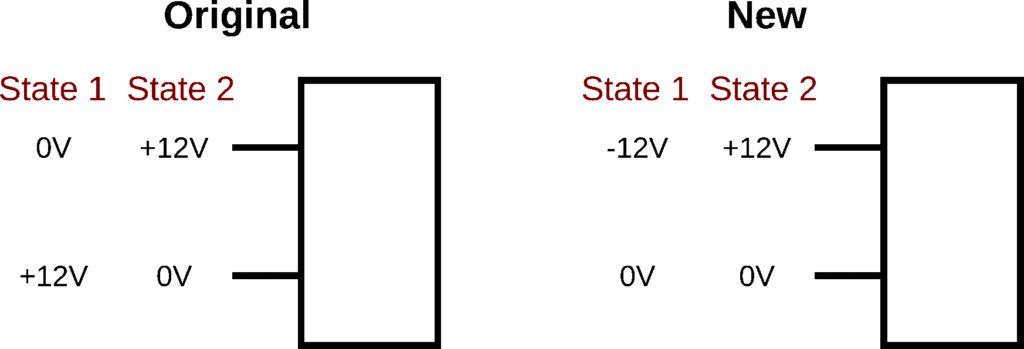
The key difference is that in the original scheme each point motor needs two separately switched wires. In the new arrangement only one wire is switched so we only need one pin per point plus a 0V connection which is shared by all four. But, in an additional stroke of genius, we observe that the gate controller also needs a 0V connection so this one pin can serve for that as well, leaving us with the following nine total required connections. For the station board, there are only two points (three pins) plus track so that will fit on a five pin DIN connector.
| Points | Four pins switched between +12V and -12V |
| Gate | +12V, switch and 0V (latter shared with points) |
| Track | Two pins for “Red” and “Black” rail connections |
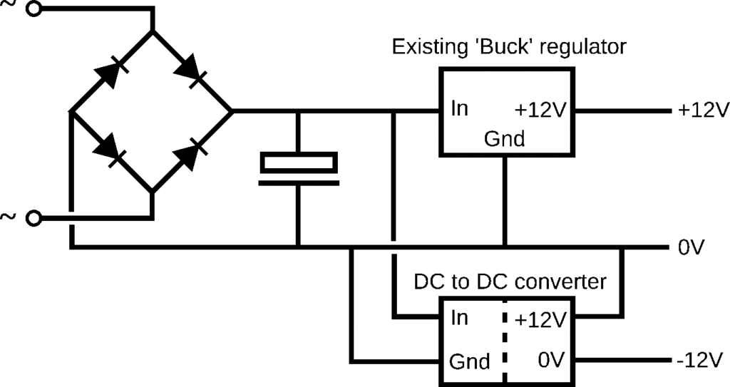
Of course, the one tiny snag with this wonderful scheme is that an additional -12V power supply is needed. I looked at various ways of adding this and finally settled on the use of an isolated DC-DC converter as shown in the diagram below. Normally this would not be the preferred solution as such converter are relatively expensive components, but fortunately I had a spare one lying around in my garage!
The next issue was how to install this modification into the control panel. As you can see below, the panel suffered from the “explosion in a wool factory” effect with wires everywhere. Buoyed up by my recent success with the gate controller I decided that the neatest solution was to replace the wiring with a custom PCB.
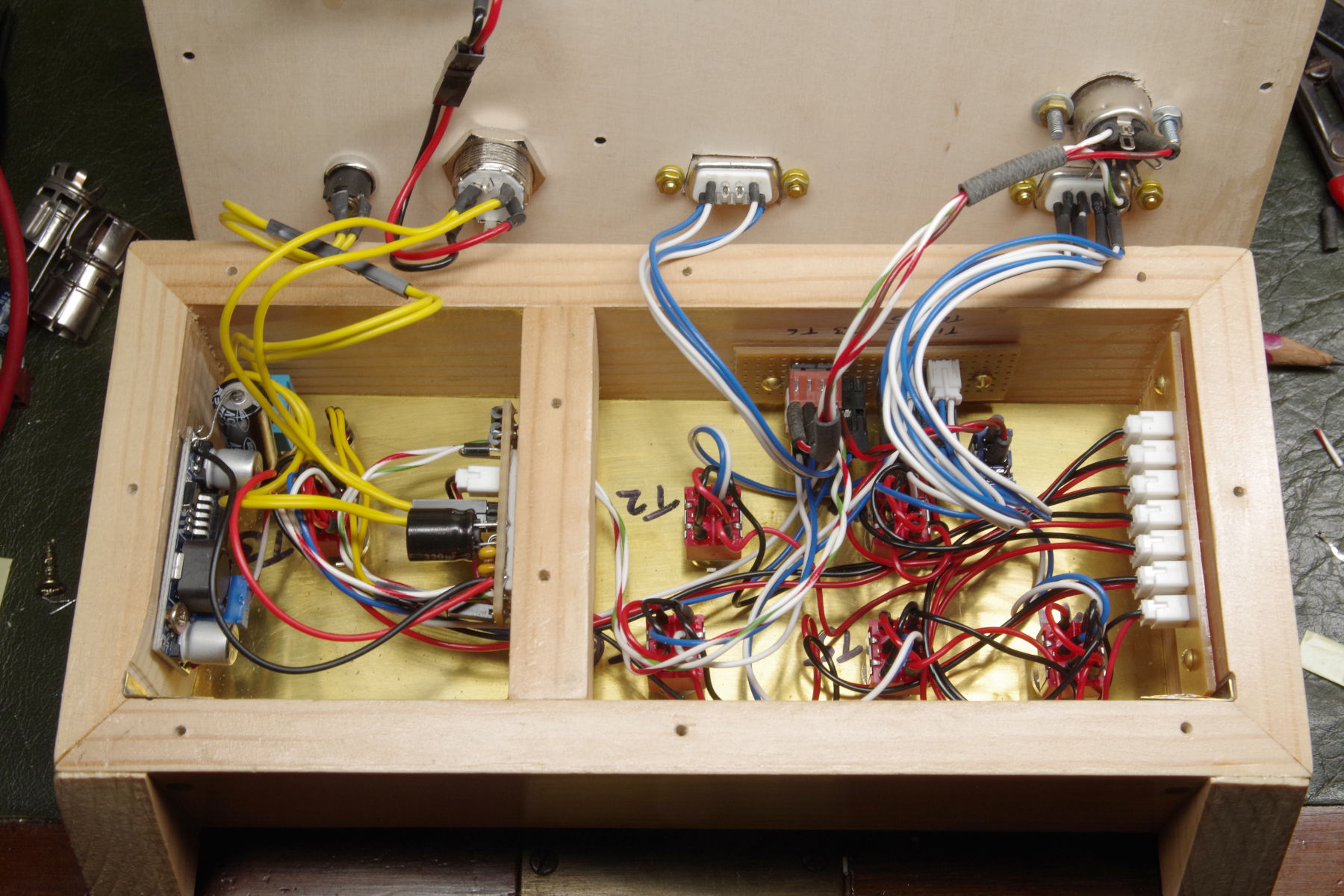
The box has a central divider which I didn’t want to remove and I would therefore need two PCBs. The obvious solution was to design a single PCB which I could saw in half, but this would exceed the 100mm x 100mm size limit for PCBWay’s special offer. The solution was to go to their main competitor JLCPCB who were a bit cheaper for these larger boards.
My next issue was the alignment of the switches. To keep the wiring simple – and indeed make the boards fit at all – I needed to use PCB mount toggle switches. Fortunately I only needed SPDT ones rather than the original DPDT but they would have to precisely line up with the holes in the brass front panel once they had been soldered onto the PCB.
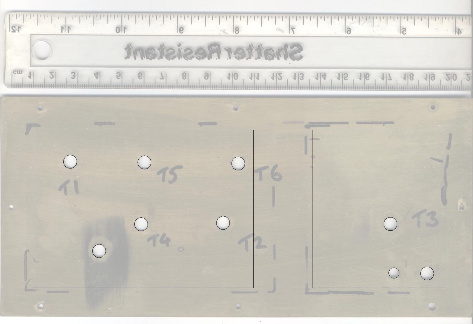
I completely removed the front panel and scanned it together with a rule for scale. I imported the scan into Inkscape and using the rule to confirm that I was working at a 1:1 scale I drew board outlines and carefully positioned circles over the holes. Finally, I imported the drawing into KiCAD and used the circles to align the switches on the PCB.
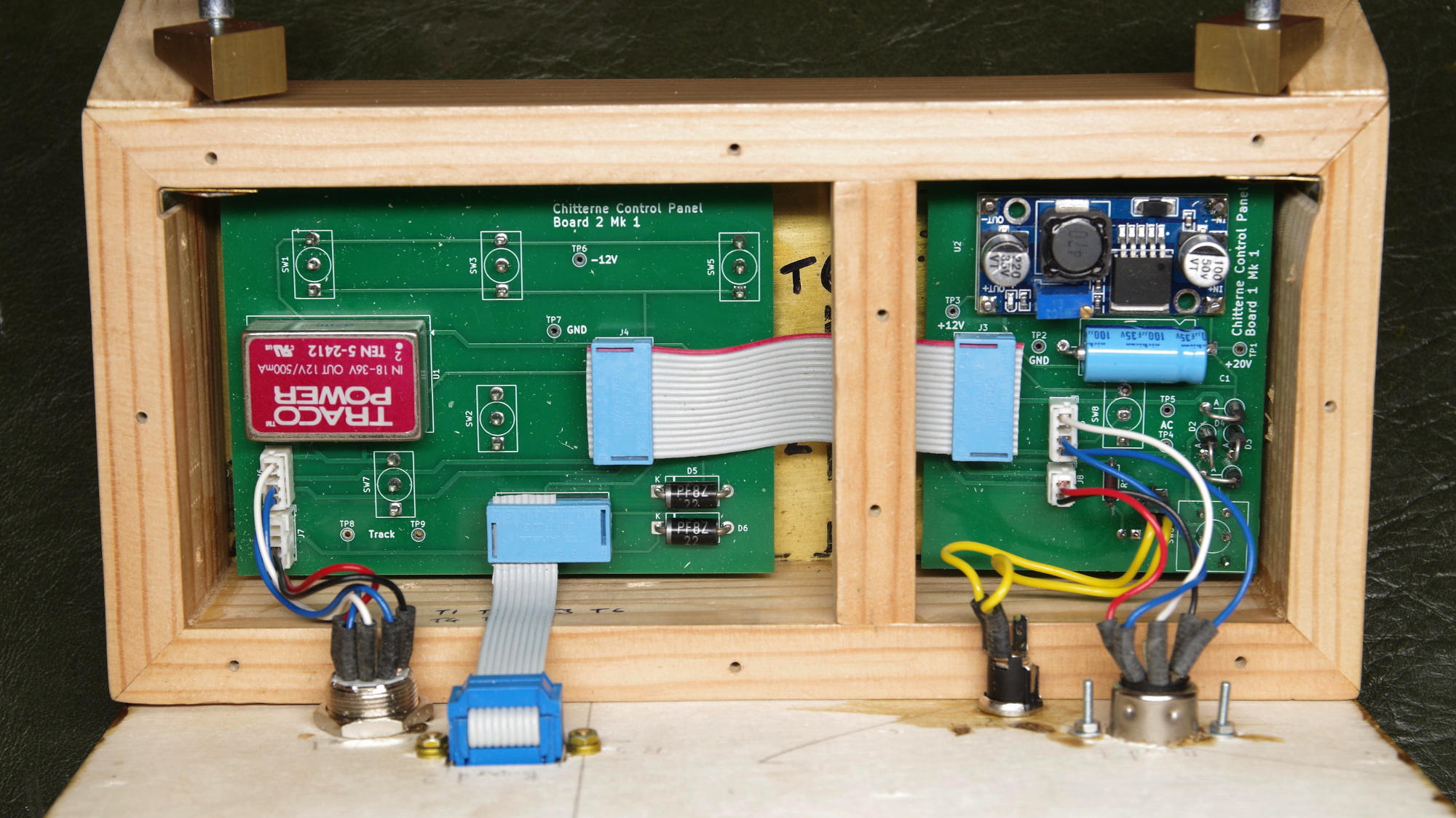
I then pressed on to finish the design of the PCBs. As usual, this was driven by my desire, so far as possible, to use components either from the old control panel or my garage and I was reasonably successful. The only items I had to purchase were the switches, an IDC 9-way D-type connector and some thin plywood to make a new back panel.
I designed the PCBs with a slot to allow me to easily separate the two halves. JLCPCB seemed to have no problem with this and the process of ordering was very similar to that with PCBWay. The boards did take a little longer to arrive (12 days as opposed to 6) but were within the promised delivery time. Total cost for five board (again, minimum order) was £8.30.
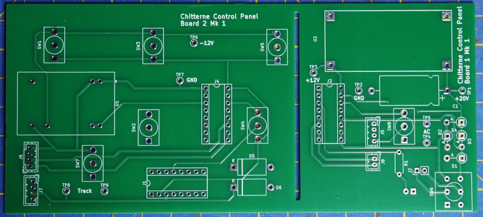
Assembling the PCB I was delighted – and slightly amazed – to find that the switches fitted perfectly. With the two PCBs connected together and the new back panel installed I tested the controller in isolation and the correct voltages were present on all the connectors.
In the next instalment I will describe the modifications to the layout wiring.