With Chitterne due to visit the Portsmouth show on the 19th November, it is time to make some vital improvements, two of which concern the control box.
I’d like to start by saying that the design and construction of the control box, carried out by Rob K, is superb and far better than anything I could have hoped to produce.
The two issues I needed to address were: the disconcerting tendency for the control panel to get hot to the touch and the addition of a new switch to control the moving gate being added by Chris H. The latter will be used to limit access to the military camp line.
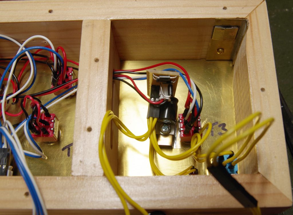
The heating ‘issue’ was caused by Rob’s ingenious decision to use the front panel as the voltage regulator heatsink. This regulator controls the 12V DC supply for the point motors – the track voltage is produced from a separate controller which runs directly from the 15V AC from the wall wart. The supply is a conventional linear one with a bridge rectifier, capacitor and regulator. The photo below shows this small board and you can see how the regulator chip is fixed to one of the front panel toggle switches.
My initial thought was to simply get a new heatsink and fix it to the back of the box. Unfortunately this is quite busy with connectors, particularly at the end with the regulator. It was at this point that I decided to think about the problem more widely and it occurred to me that perhaps instead of finding a better way to get rid of the heat I could simply not produce it in the first place! If you search online for “Buck regulator board” you will discover a huge number of people offering small switch mode regulator PCBs for very little money. I managed to buy a pack of six from Amazon for £12 (I have uses for several of these already). They are claimed to be able to deliver 3A at between 1.5 and 30V provided that the input voltage was at least 1.5V more than the output.
Now, if you think that a regulator which you buy for £2 is really going to provide 3A for any length of time then you are likely to be disappointed. However, the linear regulator Rob used was only rated for 500mA average current so I feel that we will be OK.
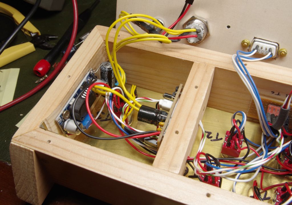
The next question was how to wire in the new regulator. In the end I decided to simply unsolder the three pin regulator (an LM2937) and connect the new regulator in its place via flying leads. The photo below shows both boards re-installed.
I temporarily connected a suitable power resistor to provide a constant 1A load and immediately noticed a problem. The output voltage fell and on inspection it seemed that the input voltage to the regulator was too low. I quickly deduced that there is insufficient capacitance after the rectifier with 330μF on the original board and 100μF on the new regulator. I therefore added another 470μF which can be seen in the top left of the above photo and this seemed to fix the problem. With a steady 1A load (which is far more than it is likely to experience in use) the new regulator became warm but not hot enough to cause any concern.
Adding the extra switch for the gate was easy in principle. The servo control board being used just requires a 12V supply and a switch which can connect a terminal to ground. Unfortunately, there were two small problems.
- The connector for the left hand baseboard (which contains the gate) was already fully occupied.
- There wasn’t a spare 12V distribution point inside the box.
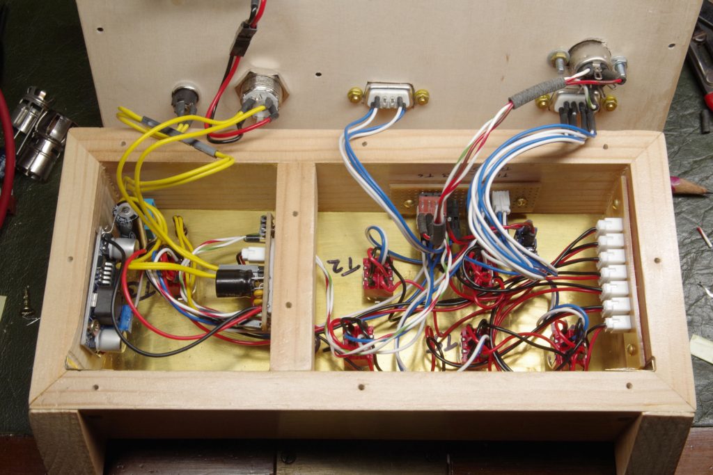
The latter issue related to Rob’s excellent engineering of the original design. Everything is connectorised so that, for example, an individual switch can be removed and replaced without any soldering being needed. Central to this solution is the power distribution board visible on the right hand side of the photo below. Unfortunately, as you can see it doesn’t contain any spare sockets for future expansion. I considered extending it, but there wasn’t room and anyway I didn’t have any of the appropriate connectors.
In the end and since time was pressing I opted for the simple solution of directly wiring the regulator to the switch distribution board visible at the back of the box from which further wires ran to a new switch on the front panel. I added a small connector and ran wires to a new DIN socket next to the existing D-type.
The use of a DIN socket obviously raises the danger of them being being plugged in the wrong way round. Fortunately, I used a seven way connector for the gate (because I had some in my garage) so this cannot be plugged into the five way controller socket. The opposite error is of course possible but I have been careful to use connections which the controller’s five way plug won’t use.
When tested last Monday the new control box worked correctly although it wasn’t able to operate the gate as the servo control board hasn’t yet been configured.
In the longer term, it might make sense to design a PCB to go into the control box which would allow the wiring to be simplified.


