A while ago now, when we could meet in person, I was discussing control systems with Roger, trying to figure out whether to go digital or analog. At the time I was using an ancient H&M and quite liked the idea of a Pentroller, having seen how well my Mashima powered test loco cruised round the group test track. Roger encouraged me to join MERG and try some of the “Pocket Money Projects” to see how I got on.
Well, I joined MERG and read a lot of material on DCC and other systems including wireless. I really liked the idea of wireless digital control with Li-ion batteries and no track wiring or cleaning, but the battery cost per locomotive is prohibitive. Finally deciding that DCC was probably what I wanted to use and that the MERG system was as good a starting point as any, especially costing significantly less than, say a Gaugemaster Prodigy, I ordered a bunch of kits and got stuck in with the soldering iron.
Well, to cut the story short, DCC works for me, I like it and will be going forward with DCC for loco control. I plan to use servos and an Android tablet to control turnouts and signals rather than motors or even wire-in-tube. That combination should mean I will not need a mimic panel or myriad of switches to control isolating sections, turnouts and signals. I also hope to implement interlocking such that a signal can only be set if the road is correctly selected, we’ll see, it’s a little ambitious. It will be down to the driver to check the road and observe the signal as the track power is always there. With DCC, a proper collision is a real possibility – part of the fun. Good job there’s a nice red friendly panic button.
So far I’ve been on quite a few Zoom calls with the Somerset MERG area group, where they all patiently indulge my questions and I have built a number of MERG kits culminating in controlling my test loco (that long-suffering ex-Lima 33) using an Android phone as the handset. I have yet to progress to the servo control part, largely because I wanted to get back to making models – remember that 1400 chassis? Nope, still not finished, but it does now run smooth. And that Mogul chassis? Yep, Mike was right, wobbly wheels.

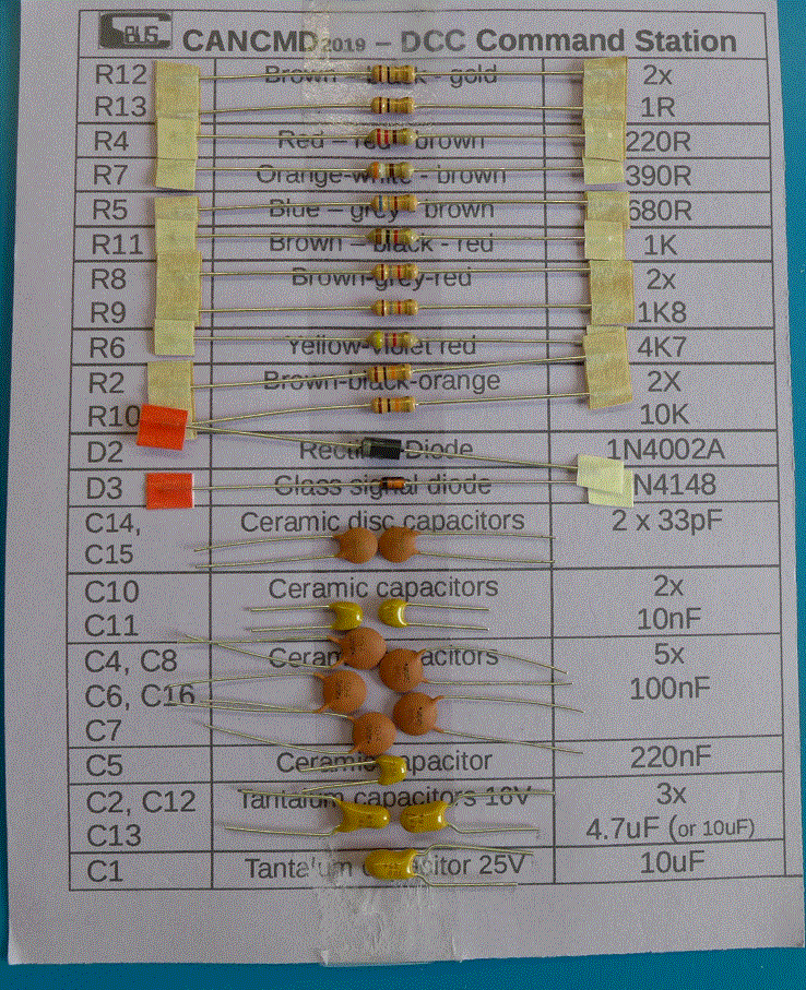
Each MERG kit is supplied with a bag of the larger parts, a component card and build instructions. There is a little bit of figuring things out, but mostly the builds are simple, almost painting-by-numbers simple. I built some of the PMP kits first:
– Track tester (it lights LEDs if there is track power, surprisingly useful)
– Logic probe (lights a red or green LED depending on high or low signal)
– CANGIZMO – a data bus tester that proved useful
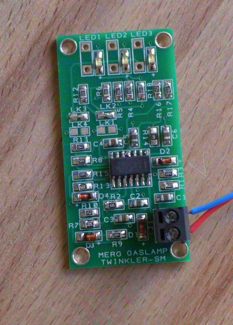
– Gas lamp twinkler – 3 LEDs that emulate gas lamp flickering, sort of

The MERG handheld controller uses surface mounted components, so I practiced on the “twinkler” PMP kit before tackling the controller. I found surface mount components to be easier to work with, but you absolutely want to get things right first time – they’re tricky to get off the circuit board once soldered in place. The usual approach to soldering works fine, everything clean, nice hot iron, in & out quick.
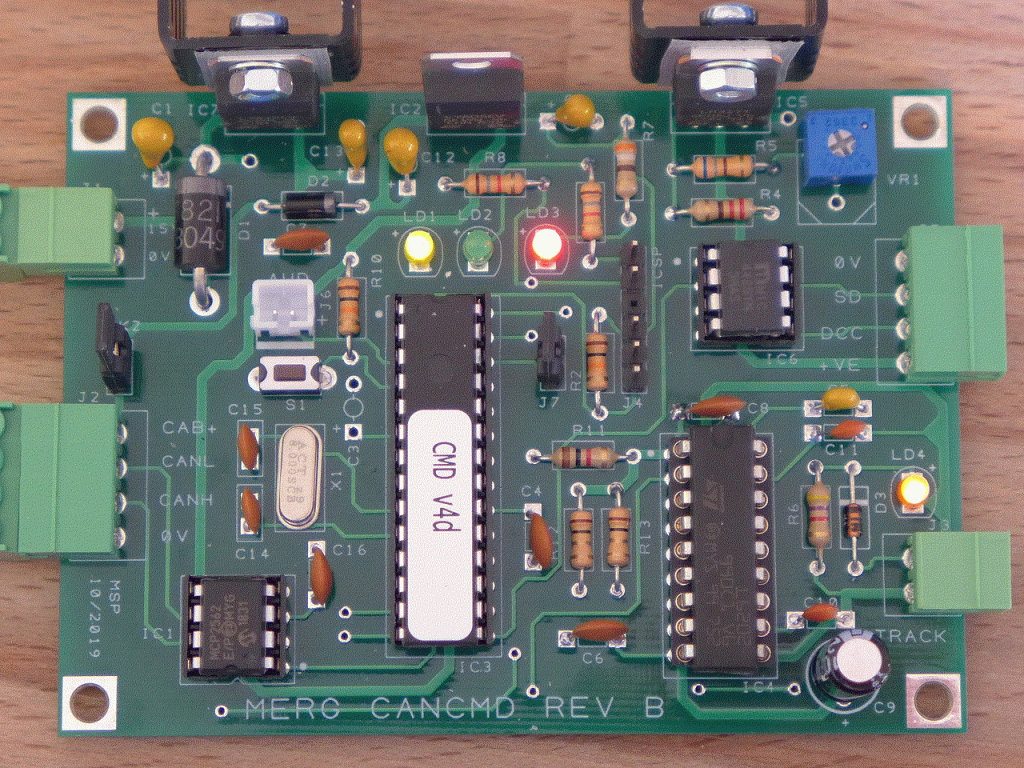
Having worked through the PMP kits, I progressed to the main event, the CANCMD command station and CANCAB handheld controller. Choosing which one to begin with was a little tricky as you need one kit working to test the other – so I just started with the command station and until I built the controller, all I could do was measure voltages and plug in the CANGIZMO to test the data bus. The build instructions generally suggest testing voltages before inserting the integrated circuits.

All the MERG kits so far have proved straightforward to build and I have had very few problems, with each one working first time. I did discover the power supplied from an old H&M controller is so poor, that the “twinkler” kit I made as a practice, did not work until I substituted the old Duette with a 9 volt battery. I made a point of using MERG power supplies for the serious work.
I adopted a methodical approach to assembly
– Check each component on the supplied card is present and correct – mistakes are made
– Fit the smallest components first, especially for through-the-hole as they’re soldered on the back
– Only take the component to be fitted from the card, leave the rest attached
– Test continuity of each component to the next site as they’re fitted (sometimes have to figure that out from the circuit diagram)
To get a simple DCC system (controller and decoder programmer) all I needed was the command station, the handheld controller and a power supply. That trio set me back c.£80 plus £20 per locomotive for the decoders, although with 1 amp of track power, that set-up can only realistically run one loco at a time (Mashima 1424 only draws 70-90mA while running light and peaks around 320mA when stalled). To run more locomotives or some of the more power hungry RTR stuff, a booster would be needed – I may need one later.
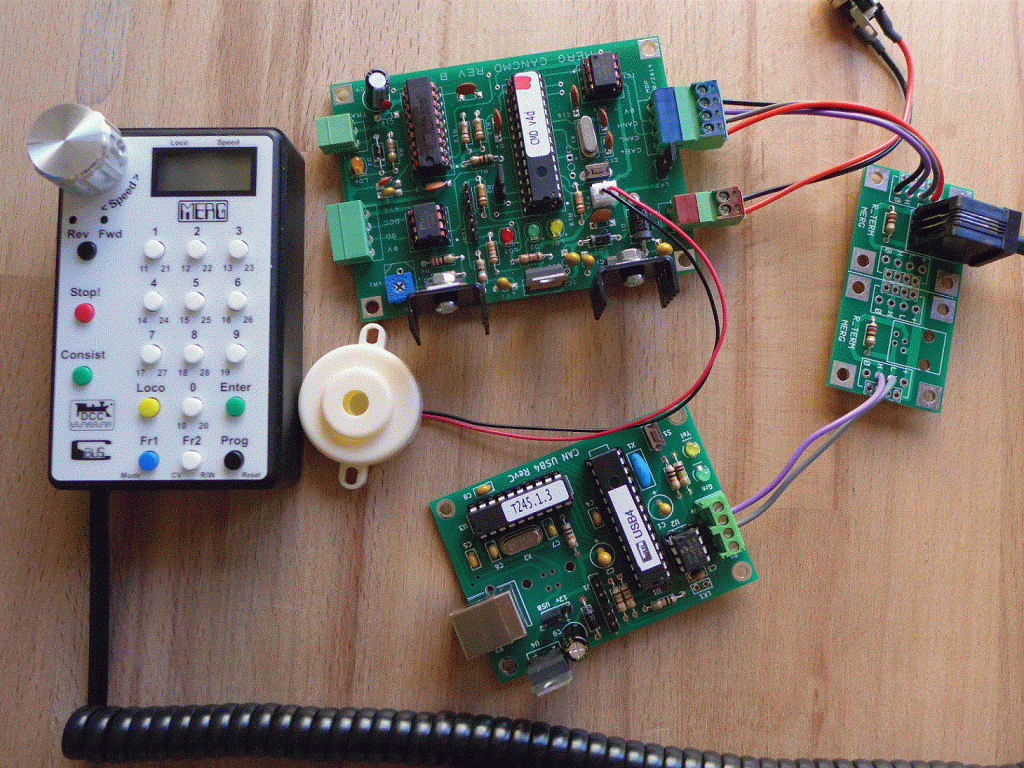
In the picture below, from top left, the handheld controller, command station, controller connector board and USB interface. The coiled cable comes with the controller kit, but you do need to get a cable for the MERG power supply. I colour coded the connectors on the right of the command station as they are the same size and shape on both sides. All the boards need mounting onto a sheet, probably MDF and then hanging on the underside of a baseboard, but otherwise, that’s a DCC system.

Certainly, DCC is more costly per locomotive as you have to add a decoder, but for me, the convenience and simplified wiring is worth it. I could probably get the same degree of smooth speed control with a decent analog controller, but with DCC I do not need to think about which switches are thrown nor will I need those switches in the first place or the panel to put them on. Just check the road, watch the signal and drive the train. I also like the idea of being able to program each locomotive to behave differently and it’s possible the option of controlling lights might be useful, one day. Sound though, certainly won’t be a feature I will be exploring.
I found that to get fine and smooth speed control, you need a “quality” decoder and I spent £20 on a decoder from Zimo to get very good results from the Mashima in the test loco. I tried the cheaper £10 Lais ones first (in case I blew one up) and frankly, the slow speed control and feedback options are crude at best, but really, they’re unusable. There are more expensive decoders with “stay alive” and of course sound – I may try a “stay alive” one in the future as DCC is apparently more sensitive to brief interruptions to power delivery. On my test track I have not had such problems and that’s my first ever hand-built P4 track, so for now it looks like £20 per locomotive.
Just because I could, I built a MERG USB interface, plugged it into the command station, installed JMRI software on an old laptop and controlled the test Sulzer from the laptop. By installing “Engine Driver” on an Android phone and connecting over the Train Shed’s wireless network, I have been able to control that 33 using the phone as well. It was an interesting distraction, but a phone screen just does not have the same feel as a proper controller. I have a plan, but it will involve learning how to code for Android to map in mouse controls (Engine Driver supports game controllers already) and I’m not ready for that experience yet.
I do now have a control system figured out and I do not have to think about where to put isolating sections on the track plan, just isolate around common crossings.
Thank you Roger for the sound advice and especially the words of encouragement to give it a go.
Next up is to test turnout operation with a servo, just as soon as I fix those wobbly wheels.